


Products & News
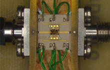
New 26GHz LNA with phenomenal performance
Celestia Callisto is proud to announce the development of its new Ka-band (25.5-27 GHz) Ambiant LNA. The...
Read more
New Contract with BKG AGGO
Celestia Callisto launches a new project for BKG’s AGGO site in Argentina
The...
Read moreOur main clients


Solutions for Space Engineering
Consultancy Services:
Studies, Project Support, Ground Station Engineering, Cryogenic Engineering and Integration, Cryogenic test Services, Training
Products Development:
Hardware and software product development for ground station including Ultra-Low Noise Cryo RF products, Ambient RF products, LNAs and measurement system for noise temperature.
Research and Development:
Technological research, studies, testing of materials and components for space communications applications
- 20+ Years of Experience in Space Industry
- More than 50 cryogenic systems delivered all over the world
- Patented designs
- Flexible, independent, reactive